What Is Parallel Slide Gate Valve?

The Application of Parallel Slide Gate Valve
Introducing high-quality High Pressure Valves from Cameron, renowned for their reliability and performance. These valves, including the advanced Velan Parallel Slide Gate Valve, are pivotal in various industries. Parallel slide gate valve animation demonstrates their efficient operation, allowing precise control of high-pressure fluids or gases. Leading parallel slide gate valve manufacturers ensure top-notch quality, durability, and adherence to industry standards. These valves find extensive use in oil and gas refineries, power generation plants, chemical processing facilities, and water treatment plants. Their robust construction and superior sealing capabilities make them indispensable for critical applications where safety, reliability, and precision are paramount. Trust Cameron for high-performance High Pressure Valves meeting the most demanding industrial requirements.
What Are The Types Of Parallel Slide Gate Valve?
- Solid Wedge Parallel Slide Gate Valve: This type of valve features a solid wedge design with parallel sliding gates. The gates move in parallel with the flow direction to open or close the valve. Solid wedge gate valves are suitable for applications requiring tight shut-off and resistance to flow erosion.
- Flexible Wedge Parallel Slide Gate Valve: Unlike solid wedge gate valves, flexible wedge gate valves have wedges that can flex or deform slightly to accommodate changes in temperature and pressure. This design helps maintain a tight seal even in conditions where there may be slight misalignment or distortion in the valve body.
What Is Parallel Slide Gate Valve?
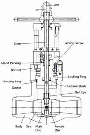
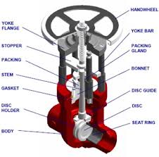
A Parallel Slide Gate Valve is a type of valve characterized by two parallel gates that slide up and down to control the flow of fluid through the valve. Unlike traditional gate valves where the gate moves perpendicular to the flow direction, in a parallel slide gate valve, the gates move parallel to the flow direction. This design minimizes friction and wear on the sealing surfaces, allowing for tighter shut-off and enhanced sealing capabilities, particularly in high-pressure and high-temperature applications. Parallel slide gate valves are commonly used in industries such as oil and gas, chemical processing, power generation, and water treatment.
How Does Parallel Slide Gate Valve Work?
The operation of a Parallel Slide Gate Valve involves two gates that slide parallel to the flow direction to control fluid flow. When the valve is open, the gates retract fully into the valve body, allowing fluid to pass through unrestricted. To close the valve, the gates slide down simultaneously to create a tight seal against the valve seat, blocking the flow of fluid. This design minimizes friction and wear, ensuring reliable shut-off and enhanced sealing capabilities, especially in high-pressure applications. The parallel movement of the gates enables precise flow control and reduces the risk of jamming or sticking, making parallel slide gate valves suitable for critical industrial applications.
Features of Parallel Slide Gate Valve
- Parallel Gates: Equipped with two parallel gates that slide vertically to control fluid flow, ensuring precise and reliable operation.
- Enhanced Sealing: The parallel movement of gates creates a tight seal against the valve seat, minimizing leakage and ensuring superior shut-off performance.
- Minimal Friction: Designed to minimize friction and wear on sealing surfaces, prolonging the valve’s service life and reducing maintenance requirements.
- High Pressure Capability: Capable of withstanding high-pressure conditions, making them suitable for applications requiring robust and dependable valves.
- Bidirectional Flow: Allows for bidirectional flow, providing versatility and flexibility in various industrial applications.
- Resilient to Erosion: Resistant to flow erosion, ensuring long-term reliability and consistent performance in demanding environments.
- Suitable for High Temperatures: Designed to withstand high temperatures, enabling operation in applications involving elevated temperature fluids or gases.
- Robust Construction: Constructed with durable materials such as stainless steel or alloy steel, ensuring durability and reliability in harsh operating conditions.
- Low Maintenance: Requires minimal maintenance due to its robust construction and minimal moving parts, reducing downtime and operational costs.
Advantages of Parallel Slide Gate Valve
- Tight Shut-off: Provides tight shut-off, minimizing leakage and ensuring efficient flow control.
- Enhanced Sealing: Offers superior sealing capabilities due to parallel movement of gates, reducing the risk of leakage.
- Bidirectional Flow: Allows for bidirectional flow, providing versatility in various industrial applications.
- Minimal Friction: Minimizes friction and wear on sealing surfaces, prolonging the valve’s service life and reducing maintenance requirements.
- Robust Construction: Constructed with durable materials, such as stainless steel or alloy steel, ensuring reliability in harsh operating conditions.
- High Pressure Capability: Capable of withstanding high-pressure conditions, making them suitable for demanding applications.
- Resistant to Erosion: Resistant to flow erosion, ensuring long-term reliability and consistent performance.
- Versatile Applications: Suitable for a wide range of industries, including oil and gas, chemical processing, power generation, and water treatment.
- Ease of Maintenance: Requires minimal maintenance due to its robust construction and simple design, reducing downtime and operational costs.
- Precise Flow Control: Allows for precise control over fluid flow rates, ensuring efficient operation of industrial processes.

The Specifications of Parallel Slide Gate Valve
| Specification | Details |
|---|---|
| Type | Parallel Slide Gate Valve |
| Ball Material | Stainless Steel, Alloy Steel, Hardened Alloys |
| Attachment Type | Flanged, Threaded, Welded, Clamp, Socket Weld |
| Thread Standard | ANSI, DIN, JIS, BS, ISO |
| Thread Size | 1/4″, 3/8″, 1/2″, 3/4″, 1″, 1-1/4″, 1-1/2″, 2″ |
| Body Material | Stainless Steel, Carbon Steel, Alloy Steel |
| Safe for Use With | Water, Oil, Gas, Chemicals, Steam, Cryogenic |
| Handle Type | Handwheel, Gear, Actuator |
| Handle Material | Aluminum, Stainless Steel, Carbon Steel |
| Maximum Working Pressure (psi) | Varies based on size and design, e.g., 1500 psi |
| Maximum Working Pressure (bar) | Varies based on size and design, e.g., 100 bar |
| Operating Pressure | Varies based on application requirements |
The Installation Steps for Parallel Slide Gate Valve
- Prepare the Work Area: Ensure the work area is clean, dry, and free from debris or contaminants that could affect the valve’s performance.
- Inspect the Valve: Check the Parallel Slide Gate Valve for any damage or defects before installation, including scratches, dents, or leaks.
- Prepare the Pipeline: Cut and prepare the pipeline according to the valve’s specifications, ensuring proper alignment and clearance for installation.
- Apply Thread Sealant: If the valve has threaded connections, apply a suitable thread sealant or tape to ensure a leak-tight seal.
- Install the Valve: Position the Parallel Slide Gate Valve in the pipeline, ensuring it is aligned correctly with the flow direction indicated by the arrow on the valve body.
- Tighten Connections: Use appropriate tools to tighten the valve connections securely, ensuring they are snug but not over-tightened to avoid damage.
- Pressure Test: Conduct a pressure test to verify the integrity of the installation and ensure there are no leaks or defects.
- Secure the Valve: Once the pressure test is successful, secure the valve in place using suitable mounting hardware or brackets to prevent movement or vibration.
- Final Inspection: Perform a final visual inspection of the installation to ensure everything is correctly aligned, tightened, and secure.
- Document Installation: Document the installation details, including valve specifications, installation date, and any test results, for future reference and maintenance purposes.
The Operation Theory of Parallel Slide Gate Valve
- Operation Theory of Parallel Slide Gate Valve:
- Parallel Slide Gate Valves operate by utilizing two parallel gates that slide up and down within the valve body.
- When the valve is open, the gates retract fully into the valve body, allowing fluid to pass through unrestricted.
- To close the valve, the gates slide down simultaneously to create a tight seal against the valve seat, blocking the flow of fluid.
- This parallel movement of the gates minimizes friction and wear on the sealing surfaces, ensuring reliable shut-off and enhanced sealing capabilities, especially in high-pressure applications.
- Comparison to Wedge Gate Valves:
- Parallel Slide Gate Valves and Wedge Gate Valves are both types of gate valves but operate differently.
- In Parallel Slide Gate Valves, the gates move parallel to the flow direction, while in Wedge Gate Valves, the gate moves perpendicular to the flow direction.
- Wedge Gate Valves typically have a single gate that wedges itself between the valve seat and the body, while Parallel Slide Gate Valves have two gates that slide parallel to each other.
- Parallel Slide Gate Valves offer tighter shut-off and enhanced sealing capabilities compared to Wedge Gate Valves, making them suitable for high-pressure applications.
- Gate Valve Parallel Slide:
- “Gate Valve Parallel Slide” is a term often used to describe the design of Parallel Slide Gate Valves.
- It emphasizes the parallel movement of the gates within the valve body, distinguishing it from other types of gate valves.
- Gate Valve Parallel Slide design ensures precise flow control, minimal friction, and superior sealing performance, making it ideal for critical industrial applications requiring reliable shut-off and precise flow regulation.
The Parameters Table of Parallel Slide Gate Valve
| Parameter | Details |
|---|---|
| Type | Parallel Slide Gate Valve |
| Body Material | Stainless Steel, Carbon Steel, Alloy Steel |
| Gate Material | Stainless Steel, Alloy Steel, Hardened Alloys |
| Seat Material | Stainless Steel, PTFE, Reinforced PTFE, Graphite |
| Stem Material | Stainless Steel, Alloy Steel, Hardened Alloys |
| Bonnet Material | Stainless Steel, Carbon Steel, Alloy Steel |
| Connection Type | Flanged, Threaded, Welded, Clamp, Socket Weld |
| Thread Standard | ANSI, DIN, JIS, BS, ISO |
| Thread Size | 1/4″, 3/8″, 1/2″, 3/4″, 1″, 1-1/4″, 1-1/2″, 2″ |
| Safe for Use With | Water, Oil, Gas, Chemicals, Steam, Cryogenic |
| Handle Type | Handwheel, Gear, Actuator |
| Handle Material | Aluminum, Stainless Steel, Carbon Steel |
| Maximum Working Pressure (psi) | Varies based on size and design |
| Maximum Working Pressure (bar) | Varies based on size and design |
| Operating Pressure | Varies based on application requirements |

